Electric Voodoo: It's Done with Magnets!
Dave Althoff, Jr.
Please note: This article was written for the European Coaster Club publication, First Drop, and appeared in Issue 53/54. Needless to say, the article is specifically targeted towards a coaster-enthusiast audience. Given the email response this article has received, I should mention that I wrote this as a research project, and as such the article pushes my understanding of the subject. I'm not an electrical engineer.
In recent years, we have seen some unusual, even amazing applications of electric motors in amusement rides, especially the adaptations and variations on linear motors. Magnetic braking can bring a speeding vehicle to a near stop cleanly and comfortably. Linear motors can launch a multi-ton vehicle to high speed in seconds. And all of this is done using systems that make no physical contact and have almost no moving parts. So how does it work?
In one sense, it's quite simple, but to understand how linear motors work, you must first understand how a rotary electric motor works, because the principle is exactly the same. Traditional rotary motors are all around us. We are so used to them that we don't think about how they work. But if we really understood how they work, linear motors would not seem so mysterious.
Fundamental concepts: Magnetism, electricity, and motion
We need to understand the connection between electricity and magnetism. Elementary Physics, usually includes a series of dramatic experiments to show this connection. First, using a bar magnet, iron filings, and a sheet of paper you can see the magnetic field lines around the magnet. Place the sheet of paper over the bar magnet ands sprinkle the iron filings over the ends of the magnet; the filings will line up with the magnetic field around the poles of the magnet. Second, if you do the same experiment, substituting a conductor...a piece of wire...for the magnet, you can demonstrate that the same magnetic field lines exist around the conductor when a current is applied as exist around the bar magnet. In other words, passing an electrical current through a conductor generates a magnetic field around that conductor.
The reverse is also true. If you move a conductor through a magnetic field, a current is induced in the conductor. In other words, if you pass a coil of wire around a bar magnet, you will generate an electric current in the wire. Move it fast enough, and you get a steady alternating current.
Synchronous motors
Now, you've probably noticed that all of these functions are reversible. With that in mind, what do you suppose will happen if you pass a current through a conductor sitting in a magnetic field? The current will pass through the conductor, setting up its own magnetic field, which will react with the external magnetic field, causing the conductor to move! More accurately, if you supply electrical energy to a wire sitting in a magnetic field, that wire will be subject to a mechanical force. If we mount a magnet on an axle and surround it with a coil of wire, then apply current to the coil, the magnet will move to align itself with the magnetic field of the coil. If we then reverse the polarity of the field, we can get the magnet to move again. If we wind two coils and hook them up in opposite polarity to one another, position the coils opposite each other to form a stator, then connect them to an alternating current power source, we can cause a magnetic field to effectively rotate around the magnet. The magnet will rotate, matching the rotation speed of the magnetic field. This is a synchronous motor, and while it is simple and powerful, it also requires some tricks be employed in order to get the magnet to start rotating. For instance, an alternating field in a pair of directly-opposed coils will not tend to start the magnet rotating, but rather oscillating. Second, the direction of rotation is unpredictable. One way to address this problem is through the use of three-phase power.
Three-phase power
(Note: Values refer to North American standards, parenthetical values to most of the rest of the world)
The AC power that comes into your house is most likely single phase 120-volt (220 volt) 60-cycle (50 cycle) AC. This means that you have a "hot" wire and a "neutral" wire, and if you put a meter between the hot wire and the ground, the instantaneous DC voltage varies continuously from about -60v to +60v (-110v to +110v), cycling every 1/60 (1/50) second. This variation is nicely periodic and if you graph it out you get a regular sine curve. Or at least that's how we will consider it for our purposes [Footnote 1].
Three-phase AC power augments this by adding two more "hot" legs, each one also oscillating in exactly the same fashion as the first. The difference is that the voltage oscillation of the second leg is delayed 1/180th (1/150th) of a second from the first, and the oscillation of the third leg is delayed 1/180th (1/150th) of a second from the second, and 1/90th (1/75th) of a second from the first.
Think of it this way. If you connect three light bulbs to the three phases of a three-phase power supply, and if you are somehow able to see the variations in brightness at 120 Hz (100 Hz) [Footnote 2], the effect will be similar to watching a set of chaser lights like those often found outlining roller coaster tracks.
Why do we care?
|
This is important because if we put three coils into the motor and connect them to the three phases of AC power available in an industrial setting, then we can easily generate a rotating magnetic field. The voltage on the coil is offset from one coil to the next in such a way that when one coil is at maximum voltage, the other two coils are at equal voltage, one increasing and one decreasing. This means that the strongest current, and thus the strongest part of the stator field will actually rotate around the stator coils at the rate of the power line frequency. If this is a typical 60 Hz (50 Hz) electric supply, that means the field will rotate at 3,600 RPM (3,000 RPM for a 50 Hz supply). The rotor magnet, then, will also rotate in sync with this field. By adding additional sets of stator coils, we can change the rate of rotation, for instance, adding a second set of coils evenly spaced with the first will provide two field oscillations per rotation, giving a rotation speed of 1,800 RPM (1,500 RPM). That is, the magnet will travel past the first set of poles in 1/60 (1/50) of a second, then past the second set of poles in the next 1/60 (1/50) of a second, making a full rotation in 1/30 (1/25) of a second. |
 |
| Voltage in a 3-phase electric motor. Bright green indicates maximum positive voltage; bright red indicates maximum negative voltage. Opposite poles shown here are opposite ends of the same motor coil. Notice how the maximum voltage progresses from pole to pole in the stator winding, creating a rotating magnetic field. |
This does not address the problem of startup. The synchronous motor operates nicely in sync with the moving field, but does not perform so well at non-synchronous speeds, as the field will tend to catch the wrong pole of the magnet and slow the motor down. There are some tricks involving the motor windings typically used in synchronous motors, but I'm not going to get into that here, because I'm really not that interested in talking about rotary motors, but rather linear motors where the coils are laid out side by side. Instead, our preferred tactic is to use a variable frequency power supply. Synchronous motors are usually single-speed devices, with the rotation speed governed by the fixed power line frequency. In our case, instead of rotating our magnet within a rotating magnetic field in just a couple of coils, we are going to accelerate it past a large number of coils one-by-one. So the usual tactics of providing special startup windings are unnecessary if we consider our device to be a multi-speed motor, and simply vary the power line frequency as the magnet starts moving. Electromechanically, how we go about varying the frequency of an AC drive is another topic altogether.
Remember, our intention was to build a linear synchronous motor. To do that, we take the same stator coils we used in the synchronous motor and lay them out flat. Now instead of rotating, our magnet will, provided we constrain it suitably, be propelled along the coil instead of rotating. What we end up with, then, is a linear synchronous motor. To control this thing, we need a variable frequency power supply and a means of monitoring the progress of the magnet so that we can switch the coil polarity in time with the magnet progress, so that we can get it to accelerate. It turns out that this control stage is the complicated bit with linear synchronous motors, but once a suitable control system is set up, the linear synchronous motor is reasonably efficient and quite powerful. We also have an advantage with the linear synchronous motor that if we can predict the acceleration of the magnet, we can position the coils to optimize their effect on the magnet.
It turns out that there is an easier way to build a three-phase linear motor, but I caution you...this is where it gets a little strange. Let's go back to our three-phase rotary synchronous motor.
Induction motors
If we remove the magnet, we can replace it with a copper coil wound around an iron core. The copper coil is wired so that the ends of the coil are tied together in a short-circuit. So there is no electrical connection to the rotor, and the rotor is non-magnetic. But the rotor is sitting in among the stator coils, and when the stator coils are energized with a 3-phase AC current, this will create a rotating magnetic field at the center of the motor. The rotor is now a conductor sitting in a moving magnetic field. That field will induce a current in the rotor winding, which will produce its own magnetic field, which will interact with the stator field causing the rotor to turn. Because the magnetic field in the rotor is induced, it will shift to remain aligned with the stator field, so this motor...an induction motor...is self-starting with a 3-phase source. It is lacking in startup torque, and once it is running, the motor rotation will lag a little behind the stator field rotation. It will accelerate until it reaches a rotational speed equal to the rotation of the magnetic field (usually some multiple of 3,600 RPM with a 60Hz power supply, just as with the synchronous motor, for the same reason), but the induced field will always be a little behind the field supplied by the field coils.
|
Now, if we lay the coils out flat again, this induction motor becomes a linear induction motor. Typically, the "rotor" or reaction plate in a linear induction motor is a non-magnetic conductor such as aluminum or copper. But in order to get a strong enough induced magnetic field it is common to back the conductor with an iron backing plate which serves to amplify the magnetic field induced in the coil. So there is a significant weight penalty. Furthermore, the air gap between the stator and the reaction plate must typically be very small, much smaller than the allowable gap for the synchronous motor, otherwise the amount of current needed for the stator coils becomes unreasonable.
By adding a second set of coils on the opposite side of the reaction plate, the larger field produced will induce a stronger field in the reaction plate, so the backing plate can be eliminated. The trade-off, of course, is that double the coils means more power is required to drive the system. Both sets of coils are synchronized, both generating a moving three-phase magnetic field. The field induces a second field in the reaction plate, and that field pushes the reaction plate forward. The nice thing about this is that because the reaction plate field is induced by the stator coil, it is not necessary to keep the field motion synchronized with the position of the reaction plate. Apply a 60Hz current to the coils, and the reaction plate happily takes off, riding a magnetic wave. How rapidly it takes off will depend on the strength of the induced field, and that, in turn, will depend on the line voltage. How fast the thing goes will actually be controlled by the spacing of the stator coils...placing the coils farther apart will cause the magnetic wave to travel a greater distance in each cycle, meaning it will move faster.
|
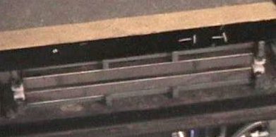
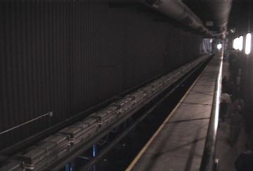
Double-sided LIMs (top) are mounted on both sides of the Flight
of Fear launch track. Aluminum reaction plates are attached to the
sides of the train. It takes four seconds and about 3 MW of electric power
to move the 20-passenger train down this launch track and accelerate it
to 54 MPH.
|
Side Effects
Just because we can apply current to a LIM coil and it will move a reaction plate doesn't mean that this is all we have to do to make our system of LIMs function. It turns out there is an important detail we need to consider. A magnetic coil, such as a motor winding, is a coil of wire with one end connected to the electrical supply leg and the other end connected to the supply neutral. Electrically, except for the coil resistance, this is nothing more than a short-circuit. Large amounts of current can flow through the coil, producing a strong magnetic field. Normally, that electromagnetic energy is converted into mechanical energy, accelerating the reaction plate. But if the reaction plate is not present, all that power will instead heat the coil, ultimately destroying it if cooling is not provided. Furthermore, in a double-sided LIM (one with two sets of stator coils with a gap in between for the reaction fin), the active coils will actually attract each other when the fin is not present, and so will attempt to collapse the mounting brackets. For those reason, some switching of the LIMs is required so that the amount of time they are active with no fin in place is limited. So the LIM installation is complicated a little by that requirement. That level of sophistication is desirable anyway because firing the LIMs in sequence will reduce the amount of power needed to operate the motor. Further control over a LIM launch comes from controlling the line voltage, which, in an AC circuit, is typically done with a high-speed switch. Modern motor controls are a complex topic by themselves, so I'm not going to get into that here.
So there you have it. In brief...
- AC electric motors come in two basic flavors, synchronous and inductive.
- Linear motors are analogous to their rotary counterparts.
- Synchronous motors propel permanent magnets (or an excited rotor coil) by interacting with the magnetic field in the rotor.
- Inductive motors propel a conductive reaction plate (or wound rotor coil) along a moving magnetic field by inducing a secondary magnetic field in the rotor.
- Both forms of linear motor operate with an air gap between the stator and rotor. The linear synchronous motor can operate with a larger air gap due to the fixed magnetic field in the reaction plate.
- Linear induction motors require either a ferrous backing plate on the reaction plate, or a matched stator coil to form a double-sided LIM in order to provide an adequate magnetic field in the reaction plate.
- For efficient operation, coil timing (power line frequency) is critical to the operation of a synchronous motor.
- The speed of an induction motor is also determined by the line frequency, but frequency is less critical than with the synchronous motor as the rotor can "catch up".
- Both for efficiency and to prevent the motor coils from overheating, linear motors work best if the stator coils are switched out when the rotor is not present.
- The synchronous speed of either motor is also determined by the pole spacing in the stator units.
Footnote 1: For you electrical engineers--It isn't really +/- 60 VDC. AC voltage ramps in a non-linear fashion (instantaneous DC voltage vs. time is actually a nice sine function) and measurements are given as RMS voltage. Basically, the recorded voltage is the statistical average voltage over a complete cycle, expressed as the root mean square of the function of the actual voltage. That's also how we get from positive-going and negative-going voltages referenced to neutral to an AC voltage given as the absolute magnitude of the voltage feeding the load. As you can see, that's very complicated and actually dips into calculus, and this explanation was intended to be as math-free as possible. Suffice to say that the numbers given in the text are not strictly accurate; they represent a convenient simplification for presenting a qualitative explanation.
Thanks to Harvey Brydon for pointing out that the numbers I originally printed here weren't right either.
Back to the text...
Footnote 2: A lamp will illuminate on both positive-going and negative-going voltage, so each phase-lamp in the example will illuminate twice in each cycle, meaning the changes in lamp brightness will be at double the phase frequency, meaning 120 Hz (100 Hz).
Back to the text...
I'd like to encourage comments, questions, corrections, and other insights on this subject. Send me your comments and I will try to address them here.
Last updated: August 21, 2010.
--Dave Althoff, Jr.
    /^\        _       *** Respect rides. They have none for you. ***
   /XXX\      /X\     /X\_      _     /X\__      _     _        _____
  /XXXXX\    /XXX\  _/XXXX\_   /X\   /XXXXX\    /X\   /X\      /XXXXX
_/XXXXXXX\__/XXXXX\/XXXXXXXX\_/XXX\_/XXXXXXX\__/XXX\_/XXX\_/\_/XXXXXX
Back to davealthoff.com...